Pantograph CCTV Intelligent Analysis System for rolling stock
Communication Systems
1. Overview
By the arrangement of the Ministry of Machinery and Vehicles of the National Railway Group on the intelligent analysis of the pantograph video monitoring system, the existing pantograph video monitoring system intelligently analyses the installation requirements, identifies pantograph mechanical structure abnormalities, electrical faults, and other problems, and assists mechanics in judging pantograph faults.
Through the analysis of the failure mode of the existing vehicle and the vehicle protection logic, mainly for pantograph failures that cannot be detected by the car itself, such as pantograph tilt, pantograph structure deformation, etc. Such failures are not easily identified during operation and lead to more severe consequences. The intelligent analysis function of the pantograph video monitoring system can analyze the pantograph video monitoring images, identify pantograph faults and make alarm prompts to assist the mechanic in judging and taking effective measures to avoid more significant hazards.
2. Pantograph CCTV System composition
The pantograph CCTV system is used to monitor the operational status of the pantographs and contact network on the roof of the train in real-time during operation. The intelligent analysis function adds intelligent identification technology to the original video monitoring system to achieve automatic real-time identification of abnormal pantograph conditions. Save videos of the working state of the pantographs during train operation and pictures of structural abnormalities in the pantographs to provide supplementary surveillance videos and analysis images for the accompanying mechanics to deal with abnormal bow network faults.
The intelligent analysis function of the pantograph CCTV system for rolling stock consists of the following main components: pantograph video monitoring server, intelligent analysis host, pantograph camera, and monitoring screen.
3. Application conditions of the intelligent analysis function of the pantograph CCTV system
The intelligent analysis function of the pantograph video monitoring system mainly identifies pantograph faults during vehicle operation. For significant pantograph faults, such as ruptured ducts and dislodged carbon skids, the pantograph will be automatically lowered without further judgment and operation by the mechanic.
This intelligent analysis function alerts for bow abnormalities that are not easily detected directly, such as pantograph tilting and pantograph structural deformation, with priority given to identifying bow structural abnormalities as they have the most severe impact.
Combined with the technical item analysis of pantograph faults in the high voltage system of the rolling stock, the application items for which the intelligent analysis function of the pantograph video monitoring system assists the mechanic in making judgments were identified as follows.
1. The pantograph is tilted during operation. At this time, the pantograph duct does not break and will not automatically lower the bow. If no alarm is provided, the tilted pantograph may be pulled by the contact network or knocked out by other foreign objects, causing severe secondary damage, so fault identification and alarm are required under this working condition.
2. Structural deformation occurs during the pantograph operation; the types of structural deformation include missing bow angles and bending deformation of the bow structure, etc., when the duct is not broken. Alarm failure may result in problems such as drilling bows, so fault identification and alarming are required for this condition.
3. Foreign objects caught in the pantograph during operation. Identification and alarm for foreign objects hanging on the bow structure and identification and notice for foreign objects on the support frame.
4. When large sparks are generated during pantograph operation, and the sparks occur in the working area, intelligent analysis functions are required to effectively identify the large sparks and provide alarms to avoid secondary accidents. Tiny sparks generated during operation are not identified, and alarm for the time being because they are not a significant hazard.
5. There is a small amount of dirt in the pantograph CCTV system camera, with a small portion at the bow structure captured by the camera when the intelligent analysis is required to allow for chunking and identification without interference from foreign objects.
4. Pantograph structure anomaly identification
4.1 Pantograph structure deformation alarm
There is a small amount of dirt in the pantograph CCTV system camera, with a small portion at the bow structure captured by the camera when the intelligent analysis is required to allow for chunking and identification without interference from foreign objects.
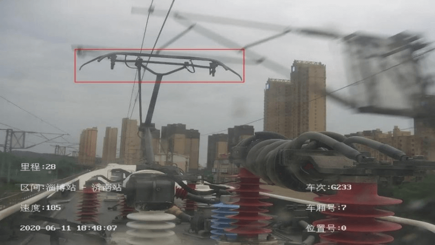
Picture of pantograph in normal condition
After running for some time, the vehicle pantograph is subjected to structural deformation by foreign object impact; it is necessary to effectively identify this type of fault and alarm through the pantograph video monitoring system; the identification picture is shown below.
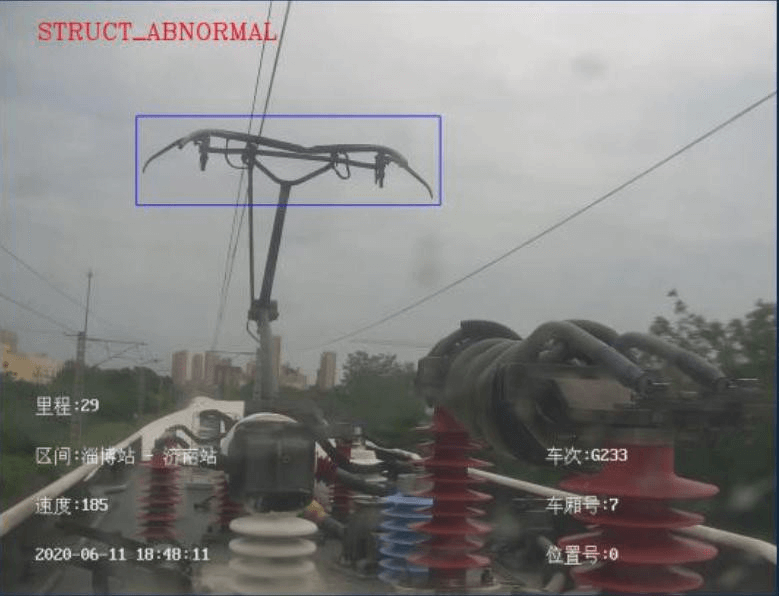
Pantograph structure failure picture
4.2 Pantograph tilt alarm
Pantograph tilt faults can occur during operation and need to be brought to the mechanic's attention in time for judgment and action. However, the structure of the pantograph and the position of the pantograph camera installed on different models are different, so the decision of the tilt angle of the pantograph is different. Combined with the relevant video of the pantograph tilt, the tilt angle of the alarm needs to be given.
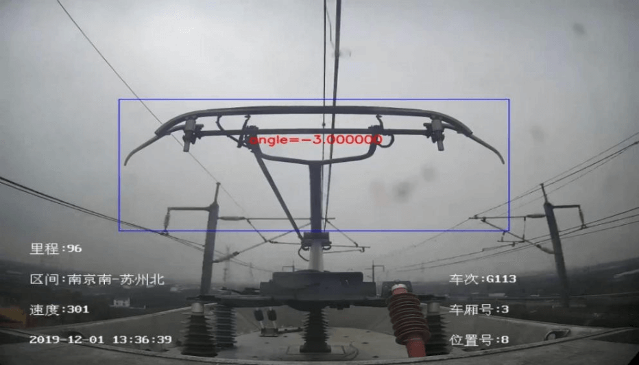
Intelligent identification of pantograph tilt angle pictures
4.3 Pantograph angle break alarm
There are two scenarios for pantograph angle breakage, one in which the angle is broken and suspended but not dislodged, and one in which the angle is broken and dislodged. Both scenarios require testing the bow integrity and sending an alarm signal to the monitoring screen when the pantograph form is incomplete. The difference lies in the trade-off threshold settings needed in both cases to reduce the rate of missed alarms. It also needs to be combined with video testing to define that an image above 40 frames in 3 seconds is a fault that will send an alarm condition.
Pictures of the pantograph lowering process
(1)Bow horn fracture not detached
The situation is as shown in the diagram below when the pantograph angle is broken and not dislodged from the fault.
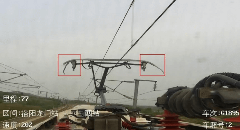
Picture of pantograph with broken bow angle not dislodged
Intelligent analysis of such situations requires correct identification of faults and alarms and actual testing of breakage without dislodging video detection.
(2)Bow angle completely broken
This type of pantograph fault needs to be identified when a complete break in the pantograph arch angle occurs, as follows.
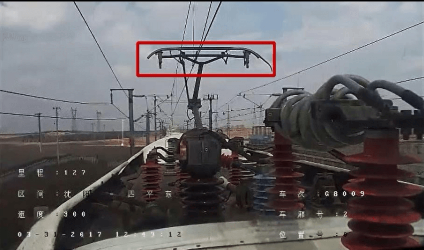
Intelligent identification of complete pantograph angle breakage
Intelligent analysis of such situations requires correct identification of faults and alarms and actual testing of breakage without dislodging video detection.
4.4 Pantograph foreign object intrusion alarm
False alarms caused by various factors are considered when the pantograph intelligent analysis mainframe identifies foreign object intrusion faults in the pantograph. Analysis from the intrusion results currently only identifies foreign object intrusion faults hanging from the bow for a long time.
(1)Pantograph body
For the intrusion of foreign objects into the bow of the pantograph, it is necessary to identify whether there is a foreign object intrusion, as shown in the diagram below, which requires the apparent detection of a foreign object in a plastic bag hanging from the pantograph of the “Fuxing” D1702.
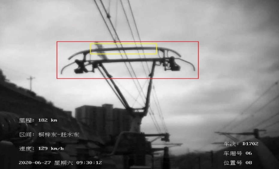
Intelligent identification of foreign objects hanging from the pantograph body
4.5 Pantograph spark alarm
Currently, tiny pantograph sparks are not analyzed for identification due to their minor impact on vehicle safety.
Pantograph intelligent analysis of pantograph sparks identifies only significant spark faults (Spark area > half of the pantograph head area; this indicator can be modified for configuration). The spark is judged to be in the working area of the carbon skid (x1 to x2, as shown in the picture below) to avoid false alarms.
The large pantograph sparks intelligent identification alarm result is shown in the following picture of the large spark intelligent identification alarm.
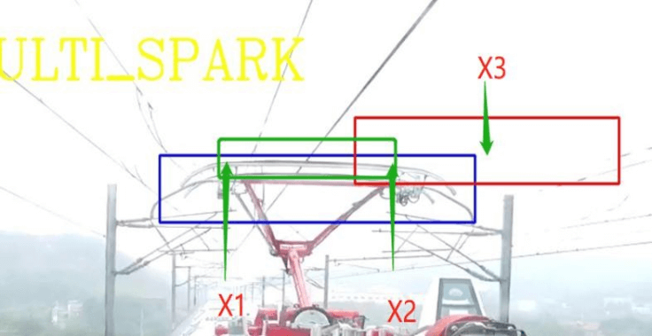
Image of the coordinates of the area where the spark occurred
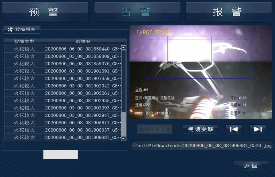
Pantograph large spark intelligent identification alarm result picture
5.Intelligent pantograph fault recognition and alarm for particular operating conditions
In opening the intelligent analysis function of the pantograph video monitoring system, special working conditions can have a significant impact on the intelligent analysis function, resulting in missed and false alarms. The following special conditions are required.
5.1 Tunnel mode alarm
During the process of entering and exiting the tunnel and running in the tunnel, the camera's exposure and the influence of the environment in the tunnel will affect the intelligent analysis function, as follows.
When entering and leaving the tunnel, algorithms need to be designed to recognize the tunnel entry and exit patterns and filter out false exposure alarms for the entry and exit tunnel entrance process. The diagram below shows that the exposure images need to be filtered out, and no warnings are made.
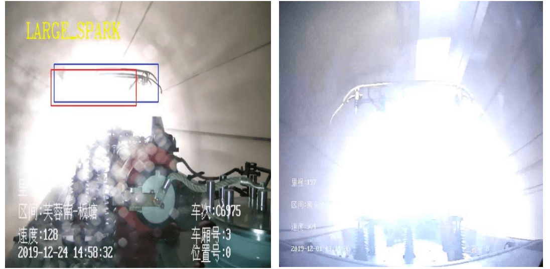
Instant exposure picture of entering the tunnel
In the tunnel, it is necessary to identify whether the current environment is suitable for detection, i.e., whether the pantograph video monitoring screen is blurred or not. If the screen is blurred due to insufficient fill light intensity or fill light failure, then the intelligent identification detection function is switched off. If it is not confusing, then detection is activated, as shown in the picture of the system generally operating in the tunnel. In addition, false alarm scenarios caused by reflections from fill lights are recommended to be included in the category of unsuitable detection, with the alarm function turned off, as shown in the picture of the bow blur caused by reflections from fill lights in the tunnel.
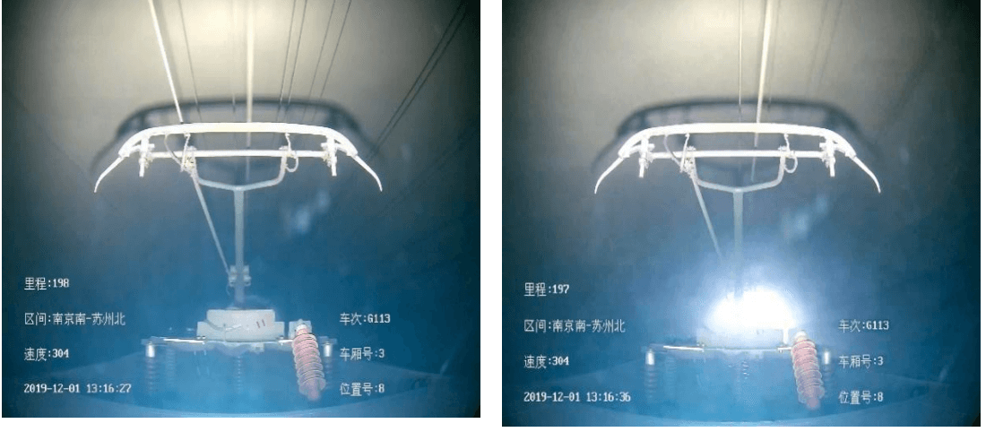
Pictures of the system in operation in the tunnel
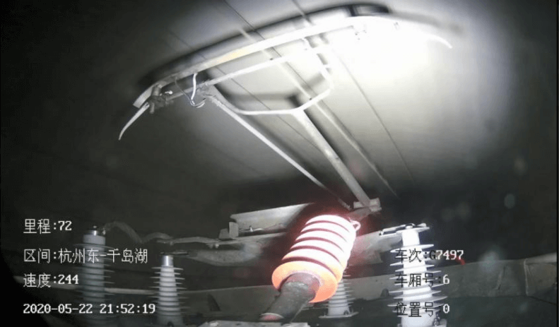
Image of bow blur caused by reflections from fill light in the tunnel
5.2 Background mode alarm
(1)Background factors such as bridges, power supply equipment
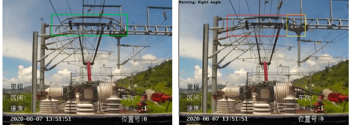
Interference caused by background factors such as bridges, power supply equipment, etc., are a few frames that will occasionally be detected as anomalies during intelligent analysis. The alarm will be triggered when there is an anomaly greater than a certain number of frames so that false images can be effectively filtered out. The specific algorithm needs to be set up in conjunction with the vehicle's speed, the time consumed by the car to pass background objects at different rates (i.e., the number of frames) is counted, and the thresholds are optimized to exclude such interference ultimately.
For example, by analyzing the background railings shown below, it was found that the train took up a total of about 4 frames as it passed through the above background facilities. The pantograph detection result is normal after 4 frames, so set that for this type of railing background. It is possible to set more than 20 frames in 1 second for normal recognition without alarm.
Background pattern interference picture
(2)Background factors for train stops
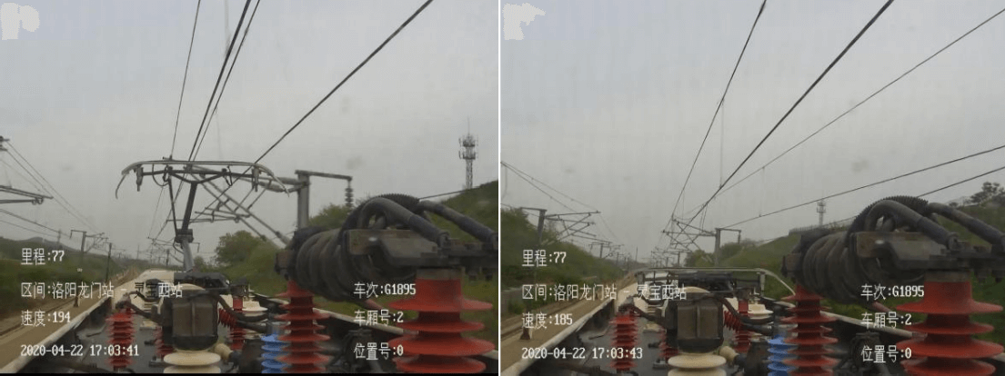
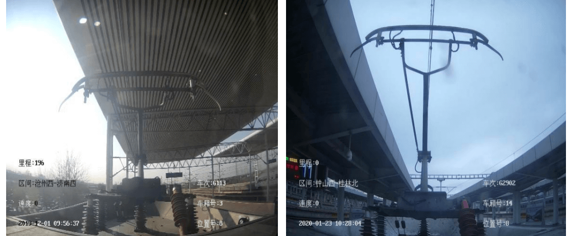
For train stops, the speed threshold needs to be set to 0, i.e., the intelligent identification function is switched off when the speed is 0. The pantograph video monitoring picture of the train stop is shown below. The image on the left shows background interference, which will give rise to false alarms. In the picture on the right, if the pantograph stops on the railing behind the image after the train has ceased to produce an overlap, false alarms will occur, so setting the speed to 0 when the intelligent analysis function is switched off will filter out such interference.
Video surveillance images of pantographs at train stops
(3)Train entry contextual factors
During the train's progress, the intelligent analysis function can be affected by false alarms due to changes in the background of the station. Due to the low-speed state, pantograph abnormalities have less impact on vehicle operation safety, and the low-speed state is less likely to cause abnormal pantograph structure problems. A certain speed threshold must be set to shield the station from false interference alarms. The pantograph video monitoring intelligent analysis function is switched off below a specific operating speed. According to the vehicle in and out of the station speed limit, tentatively set lower than 40 km / h, the speed threshold can be adjusted according to the application of the analysis to minimize the occurrence of false alarm problems.
5.3 Dirty mode alarm
The dirty mode affects the clarity of the pantograph CCTV system camera and thus the alarm of the intelligent identification function. Intelligent analysis can be switched off directly to reduce false alarms for dirty stains with a significant impact, such as sand, dust, heavy rain, or snow. For less impactful dirt, such as small smear spots, false alarms need to be reduced.
The judgment of the influence of dirt can be realized by identifying whether the video picture is blurred.

Pantograph video image clarity comparison image
The amount of dirty intrusion needs to be identified for judgment.
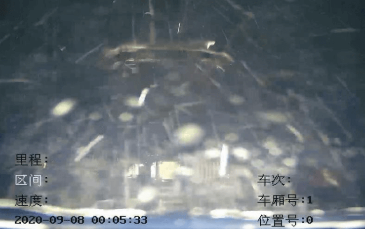
For example, as shown in the diagram below, if you set the intelligent analysis to turn off when the rainwater intrusion exceeds 30%. The graph below does not identify the pantograph as a whole, i.e., rainwater soiling encroaches on the pantograph area by more than 30%. The rain is judged to be too heavy, and the intelligent analysis is switched off. If the rainwater dirt encroaching on the pantograph area is less than a certain threshold, the intelligent identification function is not switched off.
Pantograph video surveillance images under heavy rain conditions
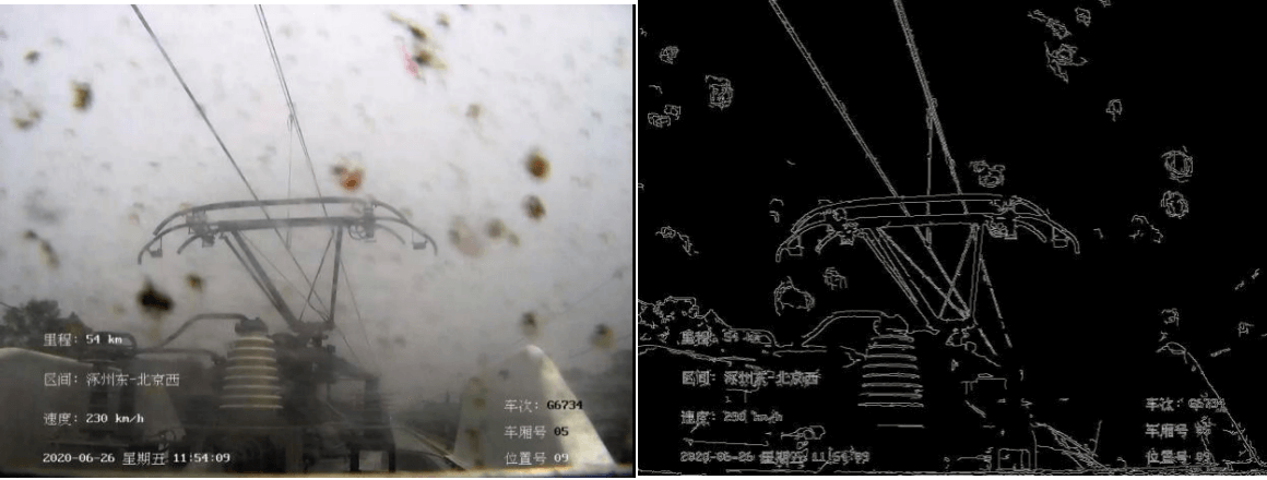
For cases where the soiling is minor, the video image is identified as edge soiled, and the overall structure of the bow is not affected; therefore, no alarm is made, as shown below.
Pictures of pantograph video surveillance affected by dirty edges
For more minor dirty cases, the dirty area of the lens is primarily fixed.
6.Client
when the intelligent analysis function detects an abnormality in the pantograph, an alarm box pops up directly on the interface of the pantograph video monitoring screen, which contains the type of pantograph fault and the fault picture. At the same time, you can click on the "Associated Video" button in the alarm box to call and play the 2-minute video where the fault picture is located (1min before and 1min after the fault alarm picture), as shown in the figure below.
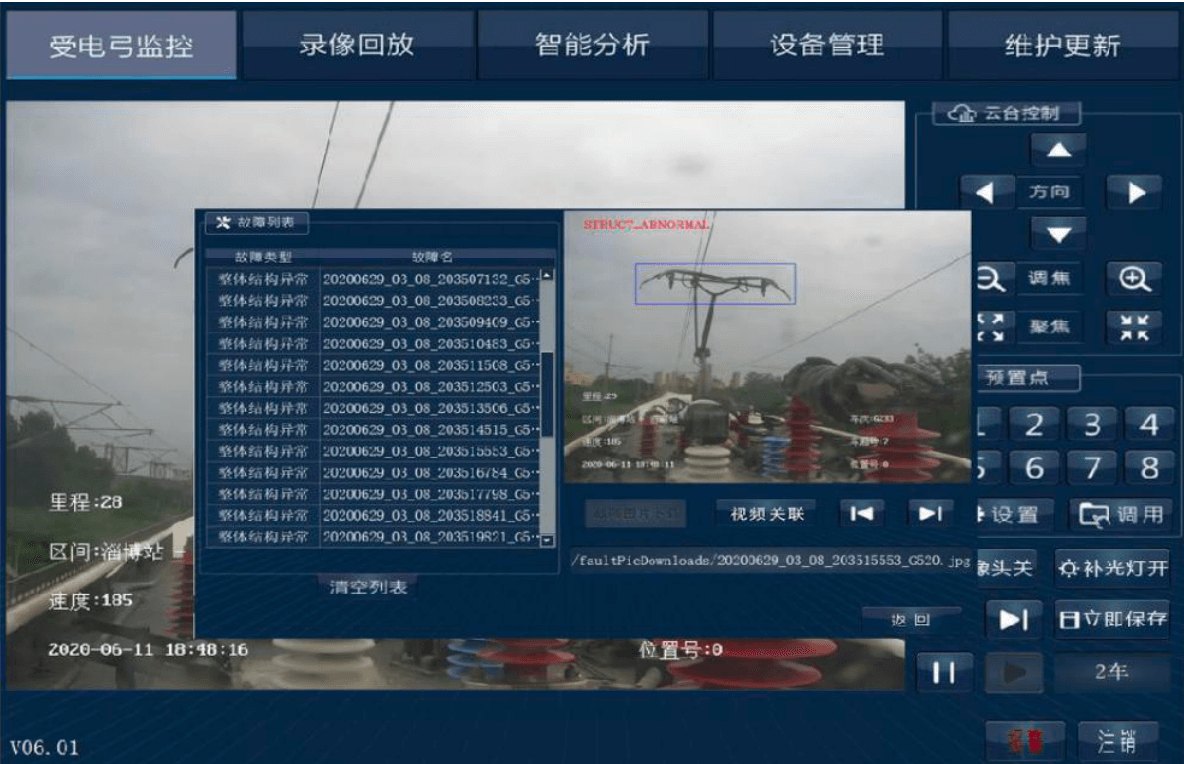
Pantograph monitoring screen fault video alarm picture
To continue reading Register Now or Login


